input 子系统介绍
参考资料
- Linux 5.x内核文档
- Documentation\input\input-programming.rst
- Documentation\input\event-codes.rst
- Linux 4.x内核文档
- Documentation\input\input-programming.txt
- Documentation\input\event-codes.txt
input 种类
- 按键:EV_KEY,比如键盘
- 相对位移:EV_REL,比如鼠标
- 绝对位移:EV_ABS,比如触摸屏
- 杂项:EV_MSC
- 软件:EV_SW
- LED:EV_LED
- 声音:EV_SND
- 会自动发出重复按键:EV_REP
- 电源开关、按键:EV_PWR
驱动框架
input device, 主要了解的是 gpio 和 uinput. uinput 主要用于用户态的键盘输入模拟用。
app 输入系统框架及调试
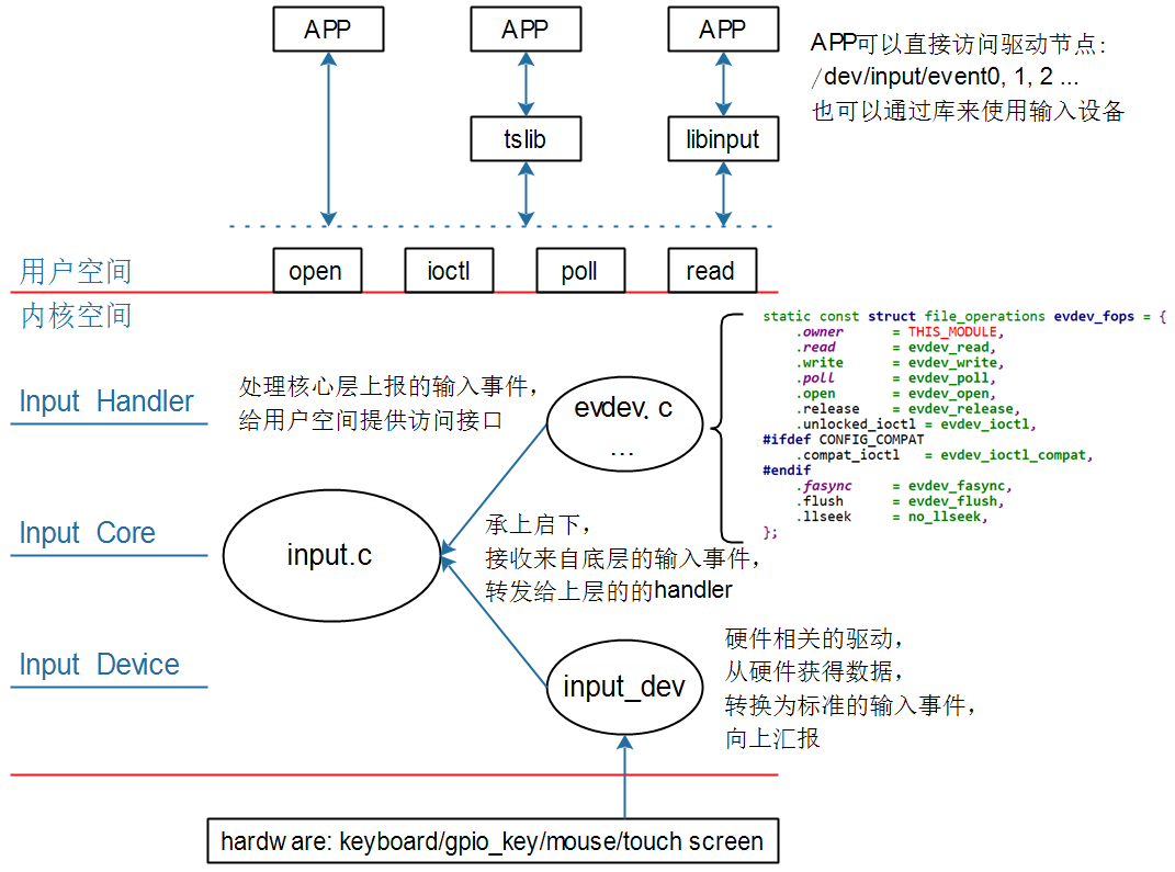
输入系统框架
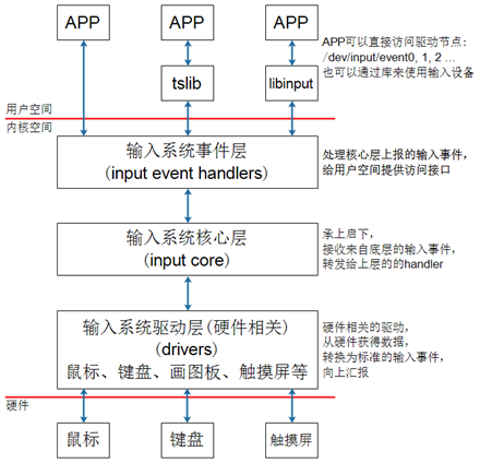
数据的流程如下:
- APP发起读操作,若无数据则休眠;
- 用户操作设备,硬件上产生中断;
- 输入系统驱动层对应的驱动程序处理中断:读取到数据,转换为标准的输入事件,向核心层汇报。所谓输入事件就是一个“struct input_event”结构体。
- 核心层可以决定把输入事件转发给上面哪个handler来处理:
- 从handler的名字来看,它就是用来处输入操作的。有多种handler,比如:evdev_handler、kbd_handler、joydev_handler等等。
- 最常用的是evdev_handler:它只是把input_event结构体保存在内核buffer等,APP来读取时就原原本本地返回。它支持多个APP同时访问输入设备,每个APP都可以获得同一份输入事件。
- 当APP正在等待数据时,evdev_handler会把它唤醒,这样APP就可以返回数据。
- APP对输入事件的处理:APP获得数据的方法有2种:直接访问设备节点(比如/dev/input/event0,1,2,...),或者通过tslib、libinput这类库来间接访问设备节点。这些库简化了对数据的处理。
调试
hexdump /dev/input/event0命令行获取输入设备当前的数据。点击触摸屏就可以看到数据刷新。ls /dev/input/* -l查看输入设备节点cat /proc/bus/input/devices查看详细的设备信息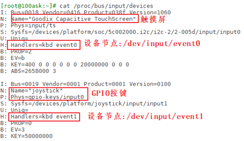
详细设备信息解析
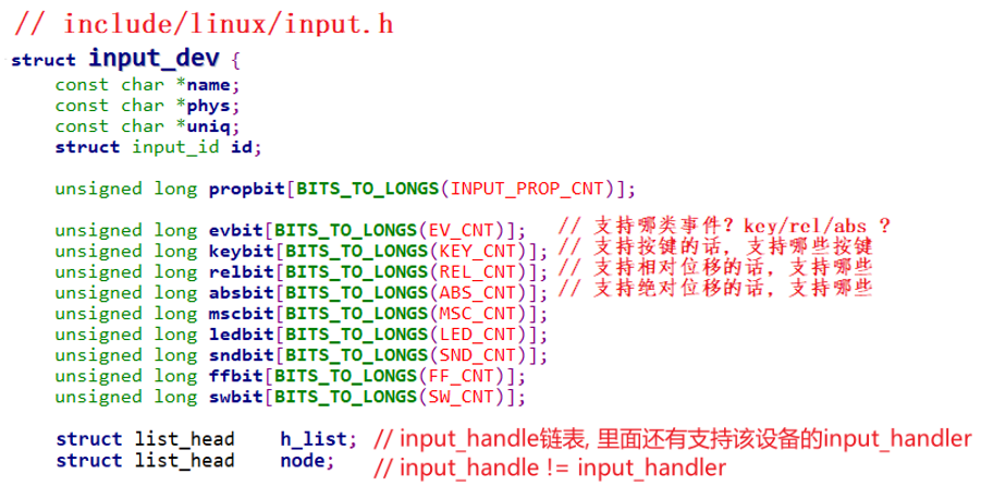
主要是 include\linux\input.h 中 struct input_dev 里面的值的表示。
struct input_dev {
    const char *name;
    const char *phys;
    const char *uniq;
    struct input_id id;

    unsigned long propbit[BITS_TO_LONGS(INPUT_PROP_CNT)];

    unsigned long evbit[BITS_TO_LONGS(EV_CNT)];
    unsigned long keybit[BITS_TO_LONGS(KEY_CNT)];
    unsigned long relbit[BITS_TO_LONGS(REL_CNT)];
    unsigned long absbit[BITS_TO_LONGS(ABS_CNT)];
    unsigned long mscbit[BITS_TO_LONGS(MSC_CNT)];
    unsigned long ledbit[BITS_TO_LONGS(LED_CNT)];
    unsigned long sndbit[BITS_TO_LONGS(SND_CNT)];
    unsigned long ffbit[BITS_TO_LONGS(FF_CNT)];
    unsigned long swbit[BITS_TO_LONGS(SW_CNT)];
...-
I:id of the device(设备ID) 该参数由结构体struct input_id来进行描述,驱动程序中会定义这样的结构体:
// include\uapi\linux\input.h struct input_id { __u16 bustype; __u16 vendor; __u16 product; __u16 version; }; - N:name of the device 设备名称
- P:physical path to the device in the system hierarchy 系统层次结构中设备的物理路径。
- S:sysfs path 位于sys文件系统的路径
- U:unique identification code for the device(if device has it) 设备的唯一标识码
- H:list of input handles associated with the device. 与设备关联的输入句柄列表。
- B:bitmaps(位图)
- PROP:device properties and quirks(设备属性)
- EV:types of events supported by the device(设备支持的事件类型)
- KEY:keys/buttons this device has(此设备具有的键/按钮)
- MSC:miscellaneous events supported by the device(设备支持的其他事件)
- LED:leds present on the device(设备上的指示灯)
B位图解析
- “B: EV=b”用来表示该设备支持哪类输入事件。b的二进制是1011,bit0、1、3为1,表示该设备支持0、1、3这三类事件,即EV_SYN、EV_KEY、EV_ABS。
- “B: ABS=2658000 3” : 表示该设备支持 EV_ABS 这一类事件中的哪一些事件。这是2个32位的数字:0x2658000、0x3,高位在前低位在后,组成一个64位的数字:“0x2658000,00000003”,数值为1的位有:0、1、47、48、50、53、54,即:0、1、0x2f、0x30、0x32、0x35、0x36,对应以下这些宏:
// include\uapi\linux\input-event-codes.h
#define ABS_X           0x00
#define ABS_Y           0x01
...
#define ABS_MT_SLOT     0x2f    /* MT slot being modified */
#define ABS_MT_TOUCH_MAJOR  0x30    /* Major axis of touching ellipse */
#define ABS_MT_TOUCH_MINOR  0x31    /* Minor axis (omit if circular) */
#define ABS_MT_WIDTH_MAJOR  0x32    /* Major axis of approaching ellipse */
#define ABS_MT_WIDTH_MINOR  0x33    /* Minor axis (omit if circular) */
#define ABS_MT_ORIENTATION  0x34    /* Ellipse orientation */
#define ABS_MT_POSITION_X   0x35    /* Center X touch position */
#define ABS_MT_POSITION_Y   0x36    /* Center Y touch position */
即这款输入设备支持上述的ABS_X、ABS_Y、ABS_MT_SLOT、ABS_MT_TOUCH_MAJOR、ABS_MT_WIDTH_MAJOR、ABS_MT_POSITION_X、ABS_MT_POSITION_Y这些绝对位置事件(它们的含义在后面讲解电容屏时再细讲)。
数据
include\uapi\linux\input.h 中的 struct input_event 就是传递的数据。
struct input_event {
    struct timeval time;
    __u16 type;
    __u16 code;
    __s32 value;
};- type
include\uapi\linux\input-event-codes.h中有 event type, 常用的就三种:#define EV_SYN 0x00 #define EV_KEY 0x01 #define EV_REL 0x02 #define EV_ABS 0x03 - code : KEY_A, ABS_X 等
#define KEY_A 30 ... #define ABS_X 0x00 - value: 0 松开,1 按下,2 长按
- 当本次的所有数据全部上传完成,就需要最后通过
EV_SYN这个事件来说明。比如下面的数据中,通过EV_SYN来表明两次按键操作。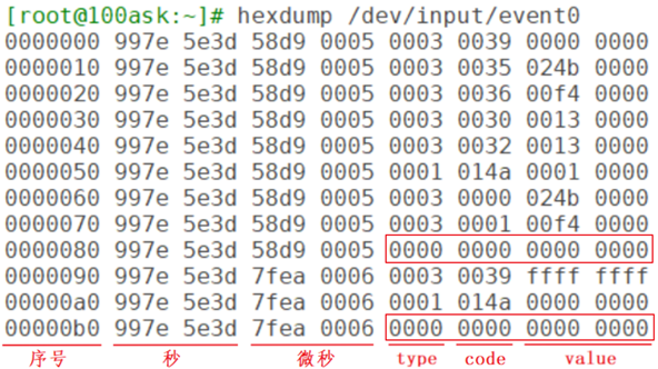
app 现场编程读取输入
evdev_do_ioctl
获取输入设备相关信息,需要使用 ioctrl, 对应的驱动在 drivers\input\evdev.c 中的 static long evdev_do_ioctl(struct file *file, unsigned int cmd, void __user *p, int compat_mode)
evdev_do_ioctl 中,会对 cmd 进行判断,输入的 cmd 会用到有关宏:
// drivers\input\evdev.c
static long evdev_do_ioctl(struct file *file, unsigned int cmd,
               void __user *p, int compat_mode)
{
    ...
    /* First we check for fixed-length commands */
    switch (cmd) {
    case EVIOCGVERSION:
        return put_user(EV_VERSION, ip);
    case EVIOCGID:
        if (copy_to_user(p, &dev->id, sizeof(struct input_id)))
            return -EFAULT;
    ...
// include\uapi\linux\input.h
#define EVIOCGID _IOR('E', 0x02, struct input_id) /* get device ID */
// include\uapi\asm-generic\ioctl.h
#define _IOR(type,nr,size) _IOC(_IOC_READ,(type),(nr),(_IOC_TYPECHECK(size)))
#define _IOC(dir,type,nr,size) \
(((dir) << _IOC_DIRSHIFT) | \ // bit 29
((type) << _IOC_TYPESHIFT) | \ // bit 8
((nr) << _IOC_NRSHIFT) | \ // bit 0
((size) << _IOC_SIZESHIFT)) // bit 16要读取输入设备的evbit时,ioctl的request要写为 EVIOCGBIT(0, size),size的大小可以由你决定:你想读多少字节就设置为多少。这个宏的定义如下:
#define EVIOCGBIT(ev,len) _IOC(_IOC_READ, 'E', 0x20 + (ev), len) /* get event bits */使用
fd = open(argv[1], O_RDWR);
err = ioctl(fd, EVIOCGID, &id);
len = ioctl(fd, EVIOCGBIT(0, sizeof(evbit)), &evbit);
app 查询 休眠唤醒
fd = open(argv[1], O_RDWR | O_NONBLOCK);
len = read(fd, &event, sizeof(event));
app poll select 读取
    struct pollfd fds[1];
    nfds_t nfds = 1;
    fd = open(argv[1], O_RDWR | O_NONBLOCK);
    while (1)
    {
        fds[0].fd = fd;
        fds[0].events  = POLLIN;
        fds[0].revents = 0;
        ret = poll(fds, nfds, 5000);
        if (ret > 0)
        {
            if (fds[0].revents == POLLIN)
            {
                while (read(fd, &event, sizeof(event)) == sizeof(event))
                {
                    printf("get event: type = 0x%x, code = 0x%x, value = 0x%x\n", event.type, event.code, event.value);
                }
            }
        }
        else if (ret == 0)
        {
            printf("time out\n");
        }
        else
        {
            printf("poll err\n");
        }
    }
int nfds;
struct timeval tv;
fd_set readfds;
while (1)
{
/* 设置超时时间 */
tv.tv_sec = 5;
tv.tv_usec = 0;
/* 想监测哪些文件? */
FD_ZERO(&readfds); /* 先全部清零 */
FD_SET(fd, &readfds); /* 想监测fd */
/* 函数原型为:
int select(int nfds, fd_set *readfds, fd_set *writefds,
fd_set *exceptfds, struct timeval *timeout);
* 我们为了"read"而监测, 所以只需要提供readfds
*/
nfds = fd + 1; /* nfds 是最大的文件句柄+1, 注意: 不是文件个数, 这与poll不一样 */
ret = select(nfds, &readfds, NULL, NULL, &tv);
if (ret > 0) /* 有文件可以提供数据了 */
{
/* 再次确认fd有数据 */
if (FD_ISSET(fd, &readfds))
{
while (read(fd, &event, sizeof(event)) == sizeof(event))
{
printf("get event: type = 0x%x, code = 0x%x, value = 0x%x\n", event.type, event.code, event.value);
}
}
}
else if (ret == 0) /* 超时 */
{
printf("time out\n");
}
else /* -1: error */
{
printf("select err\n");
}
}app 异步读取数据
int fd;

void my_sig_handler(int sig)
{
    struct input_event event;
    while (read(fd, &event, sizeof(event)) == sizeof(event))
    {
        printf("get event: type = 0x%x, code = 0x%x, value = 0x%x\n", event.type, event.code, event.value);
    }
}

    /* 注册信号处理函数 */
    signal(SIGIO, my_sig_handler);

    /* 打开驱动程序 */
    fd = open(argv[1], O_RDWR | O_NONBLOCK);
    /* 把APP的进程号告诉驱动程序 */
    fcntl(fd, F_SETOWN, getpid());

    /* 使能"异步通知" */
    flags = fcntl(fd, F_GETFL);
    fcntl(fd, F_SETFL, flags | FASYNC);

    while (1)
    {
        printf("main loop count = %d\n", count++);
        sleep(2);
    }
电阻屏和电容屏
电阻屏
// 按下时:
EV_KEY   BTN_TOUCH     1        /* 按下 */
EV_ABS   ABS_PRESSURE  1        /* 压力值,可以上报,也可以不报,可以是其他压力值 */
EV_ABS   ABS_X         x_value  /* X坐标 */
EV_ABS   ABS_Y         y_value  /* Y坐标 */
EV_SYNC  0             0        /* 同步事件 */

// 松开时:
EV_KEY   BTN_TOUCH     0        /* 松开 */
EV_ABS   ABS_PRESSURE  0        /* 压力值,可以上报,也可以不报 */
EV_SYNC  0             0        /* 同步事件 */
电容屏
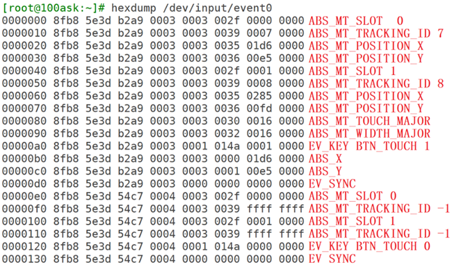
参考文档:Linux内核Documentation\input\multi-touch-protocol.rst。
// 当有2个触点时(type, code, value):
EV_ABS   ABS_MT_SLOT 0                  // 这表示“我要上报一个触点信息了”,用来分隔触点信息
EV_ABS   ABS_MT_TRACKING_ID 45          // 这个触点的ID是45
EV_ABS   ABS_MT_POSITION_X x[0]         // 触点X坐标
EV_ABS   ABS_MT_POSITION_Y y[0]         // 触点Y坐标
EV_ABS   ABS_MT_SLOT 1                  // 这表示“我要上报一个触点信息了”,用来分隔触点信息
EV_ABS   ABS_MT_TRACKING_ID 46          // 这个触点的ID是46
EV_ABS   ABS_MT_POSITION_X x[1]         // 触点X坐标
EV_ABS   ABS_MT_POSITION_Y y[1]         // 触点Y坐标
EV_SYNC  SYN_REPORT        0            // 全部数据上报完毕

// 当ID为45的触点正在移动时
EV_ABS   ABS_MT_SLOT 0   // 这表示“我要上报一个触点信息了”,之前上报过ID,就不用再上报ID了
EV_ABS   ABS_MT_POSITION_X x[0]   // 触点X坐标
EV_SYNC  SYN_REPORT         0     // 全部数据上报完毕

// 松开ID为45的触点时(在前面slot已经被设置为0,这里这需要再重新设置slot,slot就像一个全局变量一样:如果它没变化的话,就无需再次设置):
// 刚刚设置了ABS_MT_SLOT为0,它对应ID为45,这里设置ID为-1就表示ID为45的触点被松开了
EV_ABS   ABS_MT_TRACKING_ID -1
EV_SYNC  SYN_REPORT         0    // 全部数据上报完毕

// 最后,松开ID为46的触点:
EV_ABS   ABS_MT_SLOT 1       // 这表示“我要上报一个触点信息了”,在前面设置过slot 1的ID为46
EV_ABS   ABS_MT_TRACKING_ID -1  // ID为-1,表示slot 1被松开,即ID为46的触点被松开
EV_SYNC  SYN_REPORT             // 全部数据上报完毕
调试数据
hexdump /dev/input/event0
一个手指
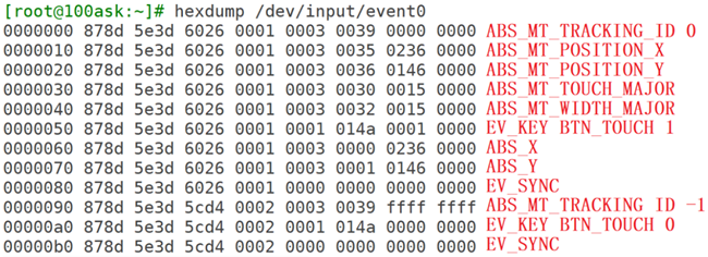
- 电容屏的实际触摸数据,为了兼容以前,后面还按照电阻屏的模式增加了电阻屏数据。
- 只有一个手指的时候,没有
EV_ABS ABS_MT_SLOT数据 - 触点是椭圆形,长轴是
ABS_MT_TOUCH_MAJOR,短轴是ABS_MT_TOUCH_MINOR - 手指也是椭圆形,长轴是
ABS_MT_WIDTH_MAJOR,短轴是ABS_MT_WIDTH_MINOR
多个手指
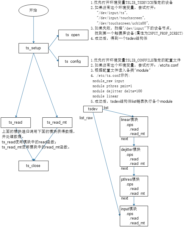
app tslib 框架
框架
源码
ts_dev 结构体。
ts_setup
ts_open
获取触摸屏设备从前到后:
- 检查参数中的设备名 dev_name
- 检查环境变量
getenv("TSLIB_TSDEVICE") - 三个默认设备节点:
static const char * const ts_name_default[] = { "/dev/input/ts", "/dev/input/touchscreen", "/dev/touchscreen/ucb1x00", NULL }; - scan_devices() 扫描
/dev/input下的设备节点。
获取了触摸屏设备之后,就 ts_open.
ts_config
配置文件的选择从前到后:
- 环境变量:
getenv("TSLIB_CONFFILE) - 预先设置的配置文件:
TS_CONF正常就是/etc/ts.conf, 主要内容如下:module_raw input module pthres pmin=1 module dejitter delta=100 module linear
ts_read, ts_read_mt
通过链表中的 next 指针,调用前级 module.
app ts_lib 交叉编译
配置编译工具链
export ARCH=arm
export CROSS_COMPILE=arm-linux-gnueabihf-
export PATH=$PATH:/home/book/100ask_imx6ull-sdk/ToolChain/gcc-linaro-6.2.1-2016.11-x86_64_arm-linux-gnueabihf/bin
交叉编译tslib
./configure --host=arm-linux-gnueabihf  --prefix=/
make
make install DESTDIR=$PWD/tmp
查看工具链中头文件、库文件目录
echo 'main(){}'| arm-linux-gnueabihf-gcc -E -v -把头文件、库文件放到工具链目录下
cd tslib-1.21/tmp/
cp include/* /home/book/100ask_imx6ull-sdk/ToolChain/gcc-linaro-6.2.1-2016.11-x86_64_arm-linux-gnueabihf/bin/../arm-linux-gnueabihf/libc/usr/include
cp -d lib/*so*  /home/book/100ask_imx6ull-sdk/ToolChain/gcc-linaro-6.2.1-2016.11-x86_64_arm-linux-gnueabihf/bin/../arm-linux-gnueabihf/libc/usr/lib/
测试tslib
cp  /mnt/tslib-1.21/tmp/lib/*  -drf     /lib
cp  /mnt/tslib-1.21/tmp/bin/*            /bin
cp  /mnt/tslib-1.21/tmp/etc/ts.conf  -d  /etc
mv /etc/init.d/S07hmi /root
reboot
ts_test_mtapp 基于 tslib 的测试程序
直接读取 /dev/input/event0 的数据需要自己处理,使用 tslib 就会非常简单,调用 ts_read_mt 这个函数就可以一次拿到所有的触摸数据。
int ts_read_mt(struct tsdev *ts, struct ts_sample_mt **samp, int max_slots, int nr); 中,nr 表示要读几次数据,max_slots 表示每次读几个点的数据,ts_sample_mt 这个是数据格式。触摸过程中,可能有手指的变化,这种情况,在 ts_sample_mt 中通过 short valid 来表示。
整个程序的流程:
ts = ts_setup(NULL, 0);打开触摸ioctl获取 max_slotsioctl(ts_fd(ts), EVIOCGABS(ABS_MT_SLOT), &slot); max_slots = slot.maximum + 1 - slot.minimum;ret = ts_read_mt(ts, samp_mt, max_slots, 1);获取触摸数据。
input 子系统框架
参考资料:
- Linux 5.x内核文档
- Documentation\input\input-programming.rst
- Documentation\input\event-codes.rst
- Linux 4.x内核文档
- Documentation\input\input-programming.txt
- Documentation\input\event-codes.txt
普通字符设备框架
- 确定主设备号
- 创建file_operations结构体, 填充drv_open/drv_read/drv_ioctl等函数
- 注册file_operations结构体 register_chrdev(major, &fops, name), major = 0, 自动生成 major
- 入口函数, 出口函数
- 辅助函数(帮助系统自动创建设备节点)
- class_create
- device_create
input 框架
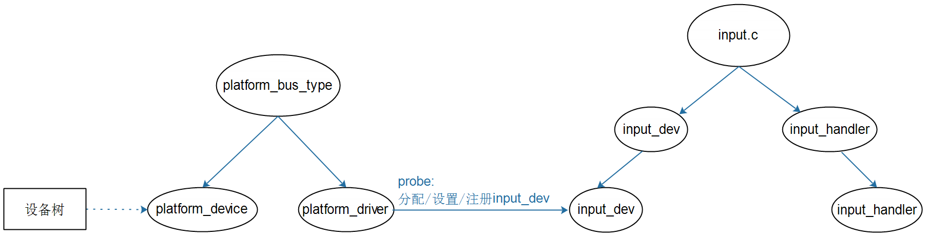
内部实现
也是分左右两边的讨论,左边是资源,右边是处理。
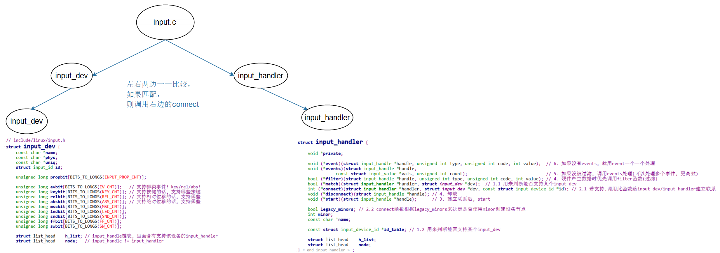
- 左边使用
int __must_check input_register_device(struct input_dev *);来注册。 - 右边使用
int __must_check input_register_handler(struct input_handler *);来注册。
左边设备资源 input_dev
右边处理 input_handler
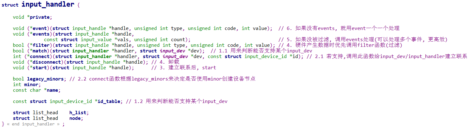
处理的时候,也是先试试 match,不行的话,再 id_table。 匹配上之后,用 connect 来连接。
connect
在 drivers\input\evdev.c 中的 static int evdev_connect(struct input_handler *handler, struct input_dev *dev, const struct input_device_id *id).
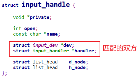
error = input_register_handle(&evdev->handle);把 input_dev 和 input_handler 保存到 handle 中,并注册. 而且还会把这个 handle 分别放到 input_dev 和 input_handler 各自结构体的链表 h_list 中。cdev_init(&evdev->cdev, &evdev_fops);error = cdev_add(&evdev->cdev, evdev->dev.devt, 1);
h_list 链表,表明一个 input_dev 可以有多个 input_handler 来进行处理,一个 input_handler 也可以有多个 input_dev 需要处理。
资源和处理的关系 input_handle
设备获取、上报数据:input_event
struct input_event {
    struct timeval time;
    __u16 type;
    __u16 code;
    __s32 value;
};
有 input_event 之后,需要先用 input_handler->filter 进行过滤,如果通过,再用 input_handler->events 来处理,实在不行,才用 input_handler->event 来处理。
注册流程
drivers\input\input.c 中的 int input_register_device(struct input_dev *dev)
list_add_tail(&dev->node, &input_dev_list);把节点加入到链表中。list_for_each_entry(handler, &input_handler_list, node)input_attach_handler(dev, handler);遍历所有 handler,然后尝试 match, 再 connect.input_handler_list中含有evdev_handler, 因为 evdev 在 init 的时候,调用了input_register_handler(&evdev_handler);把自己注册到了input_handler_list中。 所以,才能在 input_register_device 是,通过 connect 来调用 evdev 的evdev_connect.- 在
evdev_connect中,先分配evdev = kzalloc(sizeof(struct evdev), GFP_KERNEL);, 再设置evdev->handle, 然后再input_register_handle注册// device evdev->handle.dev = input_get_device(dev); // handler evdev->handle.handler = handler; input_register_handle中,把 handle 分别加入 device 和 handler 的链表中。if (handler->filter) list_add_rcu(&handle->d_node, &dev->h_list); else list_add_tail_rcu(&handle->d_node, &dev->h_list); mutex_unlock(&dev->mutex); list_add_tail_rcu(&handle->h_node, &handler->h_list);cdev_init(&evdev->cdev, &evdev_fops);,error = cdev_add(&evdev->cdev, evdev->dev.devt, 1);注册字符设备。error = device_add(&evdev->dev);增加到设备管理中,加入 /dev, /sysfs 中,与 udev 更加紧密。
app 使用流程
open
open("/dev/input/event0"), 首先会调用 evdev 中的 open,static int evdev_open(struct inode *inode, struct file *file)evdev_open中,先创建 app 对应的 client,struct evdev_client *client;; 然后再evdev_attach_client(evdev, client);把 client 加入到列表中list_add_tail_rcu(&client->node, &evdev->client_list);; 这样同一个输入设备,可以让多个 app 来使用。static void evdev_attach_client(struct evdev *evdev, struct evdev_client *client), 在 device 层,使用input_dev表示一个输入设备;在 handler 层,使用evdev来表示一个输入设备。
read
使用 evdev 的 read, static ssize_t evdev_read(struct file *file, char __user *buffer, size_t count, loff_t *ppos) 会在 evdev->wait 上休眠。
            error = wait_event_interruptible(evdev->wait,
                    client->packet_head != client->tail ||
                    !evdev->exist || client->revoked);
当设备按下之后,会产生中断,并调用 input_event 来上报,void input_event(struct input_dev *dev, unsigned int type, unsigned int code, int value)
input_event调用input_handle_event(dev, type, code, value);再调用input_pass_values(dev, dev->vals, dev->num_vals);- 在
static void input_pass_values(struct input_dev *dev, struct input_value *vals, unsigned int count)中 遍历并调用 handler:list_for_each_entry_rcu(handle, &dev->h_list, d_node) if (handle->open) { count = input_to_handler(handle, vals, count); if (!count) break; } static unsigned int input_to_handler(struct input_handle *handle, struct input_value *vals, unsigned int count)会先调用 filter,然后再 events, 再 event.if (handler->filter) ... if (handler->events) handler->events(handle, vals, count); else if (handler->event) for (v = vals; v != vals + count; v++) handler->event(handle, v->type, v->code, v->value);static void evdev_events(struct input_handle *handle, const struct input_value *vals, unsigned int count)中,会 遍历所有的 client 列表,然后传数据evdev_pass_values.list_for_each_entry_rcu(client, &evdev->client_list, node) evdev_pass_values(client, vals, count, ev_time);static void evdev_pass_values(struct evdev_client *client, const struct input_value *vals, unsigned int count, ktime_t *ev_time)中,先传数据__pass_event(client, &event);然后再wake_up_interruptible(&evdev->wait);唤醒 client 也就是 app.static void __pass_event(struct evdev_client *client, const struct input_event *event)中,把数据都填充到 client 的 buffer 中。... client->buffer[client->tail].time = event->time; client->buffer[client->tail].type = EV_SYN; client->buffer[client->tail].code = SYN_DROPPED; client->buffer[client->tail].value = 0; ...
总结
虽然 input 有点绕,但是 input_handler 正常可以直接用 evdev 的,我们一般只需要去实现 input_dev 即可。
编写 input_dev 框架
想要实现 input_dev,有两种方法:
- 直接写一个驱动,在里面实现分配,设置,注册 input_dev. 但是这样就写死了。
- 使用 platform。
- 使用设备树, 设备树会被转化为 platform_device
- 通过设备树,然后加载 对应的 platform_driver
- 在这个 platform_driver 的 probe 中,去实现 分配,设置,注册 input_dev.
总体而言,肯定使用 platform 的方法更好。
platform device
/ {
    input_dev_demo {
        compatible = "100ask,input_dev_demo";
        interrupts = <...>;
    };
};
platform driver
参考 drivers\input\keyboard\gpio_keys.c 去写。 主要做的就是 alloc, set, register 的工作。
基础框架
static const struct of_device_id input_dev_demo_of_match[] = {
    { .compatible = "100ask,input_dev_demo", },
    { },
};

static struct platform_driver input_dev_demo_driver = {
    .probe      = input_dev_demo_probe,
    .remove     = input_dev_demo_remove,
    .driver     = {
        .name   = "input_dev_demo",
        .of_match_table = input_dev_demo_of_match,
    }
};

static int __init input_dev_demo_init(void)
{
    return platform_driver_register(&input_dev_demo_driver);
}

static void __exit input_dev_demo_exit(void)
{
    platform_driver_unregister(&input_dev_demo_driver);
}

module_init(input_dev_demo_init);
module_exit(input_dev_demo_exit);

MODULE_LICENSE("GPL");
input_dev 相关
    /* alloc/set/register input_dev */
    g_input_dev = devm_input_allocate_device(dev);

    g_input_dev->name = "input_dev_demo";
    g_input_dev->phys = "input_dev_demo";
    g_input_dev->dev.parent = dev;

    g_input_dev->id.bustype = BUS_HOST;
    g_input_dev->id.vendor = 0x0001;
    g_input_dev->id.product = 0x0001;
    g_input_dev->id.version = 0x0100;

    /* set 1: which type event ? */
    __set_bit(EV_KEY, g_input_dev->evbit);
    __set_bit(EV_ABS, g_input_dev->evbit);

    /* set 2: which event ? */
    __set_bit(BTN_TOUCH, g_input_dev->keybit);
    __set_bit(ABS_MT_SLOT, g_input_dev->absbit);
    __set_bit(ABS_MT_POSITION_X, g_input_dev->absbit);
    __set_bit(ABS_MT_POSITION_Y, g_input_dev->absbit);

    /* set 3: event params ? */
    input_set_abs_params(g_input_dev, ABS_MT_POSITION_X, 0, 0xffff, 0, 0);
    input_set_abs_params(g_input_dev, ABS_MT_POSITION_Y, 0, 0xffff, 0, 0);

    error = input_register_device(g_input_dev);
中断相关
static int g_irq;
static irqreturn_t input_dev_demo_isr(int irq, void *dev_id)
{
    /* read data */

    /* report data */
    input_event(g_input_dev, EV_KEY, XX, 0);
    input_sync(g_input_dev);

    return IRQ_HANDLED;
}

    /* hardware opration */
    irq = platform_get_resource(pdev, IORESOURCE_IRQ, 0);
    g_irq = irq->start;
    request_irq(irq->start, input_dev_demo_isr, IRQF_TRIGGER_RISING, "input_dev_demo_irq", NULL);
简单触摸驱动,qemu
设备树
/ {
    input_dev_demo {
        compatible = "100ask,input_dev_demo";
        reg = <0x021B4000 16>;
        //interrupt-parent = <&gpio1>;
        //interrupts = <5 IRQ_TYPE_EDGE_FALLING | IRQ_TYPE_EDGE_RISING>;
        gpios = <&gpio1 5 1>;
    };
};- 因为用到的触摸寄存器是从 0x021B4000 开始的 4个寄存器,每个寄存器 32位,所以
reg = <0x021B4000 16>; - interrupt 直接参考其他的设备树文件去写即可。
- 正常中断直接写
interrupts即可,但是这个 qemu 的内核并不完善,所以只能用通过 gpios 转换的方式去实现。正常的内核不需要这样。
源码
gpios 转化中断引脚
参考 drivers\media\rc\gpio-ir-recv.c 中的
rc = request_any_context_irq(gpio_to_irq(pdata->gpio_nr), gpio_ir_recv_irq, IRQF_TRIGGER_FALLING | IRQF_TRIGGER_RISING, "gpio-ir-recv-irq", gpio_dev);修改自己的代码:
    int gpio;
    gpio = of_get_gpio(pdev->dev.of_node, 0);
    g_irq = gpio_to_irq(gpio);
    error = request_irq(g_irq, input_dev_demo_isr, IRQF_TRIGGER_FALLING | IRQF_TRIGGER_RISING, "input_dev_demo_irq", NULL);
调试
cat /proc/interrupts查看有没有源码中request_irq(irq->start, input_dev_demo_isr, IRQF_TRIGGER_RISING, "input_dev_demo_irq", NULL);对应的 "input_dev_demo_irq"
完善触摸驱动,qemu
需要增加 timer, 按下之后,要定时上报数据。
源码
使用定时器来自动上报数据
struct qemu_ts_con {
    volatile unsigned int pressure;
    volatile unsigned int x;
    volatile unsigned int y;
    volatile unsigned int clean;
};

static void ts_irq_timer(unsigned long _data)
{
    if (ts_con->pressure) // pressed
    {
        input_event(g_input_dev, EV_ABS, ABS_X, ts_con->x);
        input_event(g_input_dev, EV_ABS, ABS_Y, ts_con->y);
        input_sync(g_input_dev);

        mod_timer(&ts_timer,
            jiffies + msecs_to_jiffies(TOUCHSCREEN_POLL_TIME_MS));
    }

}

static irqreturn_t input_dev_demo_isr(int irq, void *dev_id)
{
    /* read data */

    /* report data */
    //input_event(g_input_dev, EV_KEY, XX, 0);
    //input_sync(g_input_dev);
    //printk("%s %s %d\n", __FILE__, __FUNCTION__, __LINE__);
    if (ts_con->pressure)
    {
        input_event(g_input_dev, EV_ABS, ABS_X, ts_con->x);
        input_event(g_input_dev, EV_ABS, ABS_Y, ts_con->y);
        input_event(g_input_dev, EV_KEY, BTN_TOUCH, 1);
        input_sync(g_input_dev);

        /* start timer */
        mod_timer(&ts_timer,
            jiffies + msecs_to_jiffies(TOUCHSCREEN_POLL_TIME_MS));
    }
    else
    {
        input_event(g_input_dev, EV_KEY, BTN_TOUCH, 0);
        input_sync(g_input_dev);

        /* cancel timer */
    }

    return IRQ_HANDLED;
}
另外,在 probe 和 remove 中需要有 新增和删除定时器。
// probe
    setup_timer(&ts_timer, ts_irq_timer, (unsigned long)NULL);
// remove
    del_timer_sync(&ts_timer);
调试
ls /dev/inputhexdump /dev/input/event3- 交叉编译 tslib, 并使用 tslib 中的测试程序来查看效果。 注意,如果想让 tslib 能够扫描到触摸屏,那么驱动中需要增加
__set_bit(INPUT_PROP_DIRECT, g_input_dev->propbit);,有这个标志位, tslib 的扫描函数才能扫描到。
gpio 按键驱动分析
参考资料:
- Linux 5.x内核
- Documentation\devicetree\bindings\input\gpio-keys.txt
- drivers\input\keyboard\gpio_keys.c
- Linux 4.x内核
- Documentation\devicetree\bindings\input\gpio-keys.txt
- drivers\input\keyboard\gpio_keys.c
- 设备树
- IMX6ULL:
Linux-4.9.88/arch/arm/boot/dts/100ask_imx6ull-14x14.dts - STM32MP157:
Linux-5.4/arch/arm/boot/dts/stm32mp15xx-100ask.dtsi - QEMU:
linux-4.9.88/arch/arm/boot/dts/100ask_imx6ull_qemu.dts
- IMX6ULL:
框架
- 右边 input 这边,input_handler 内核里面已经有了,正常不需要自己去动,只需要实现左边,也就是 input_dev 的分配设置注册。
- 为了方便不同设备的使用,input_dev 的分配设置注册,可以借用万能的 platform_bus 去实现。
- platform_bus 也是分为左右两边,左边用设备树实现即可,方便不同设备使用。在系统自动调用的右边的 platform_driver 中再去做 input_dev 的分配设置注册。
设备树
gpio-keys {
    compatible = "gpio-keys";
    pinctrl-names = "default";

    user1 {
        label = "User1 Button";
        gpios = <&gpio5 1 GPIO_ACTIVE_LOW>;
        gpio-key,wakeup;
        linux,code = <KEY_1>;
    };

    user2 {
        label = "User2 Button";
        gpios = <&gpio4 14 GPIO_ACTIVE_LOW>;
        gpio-key,wakeup;
        linux,code = <KEY_2>;
    };
};- 必备:
compatible = "gpio-keys"; - 可选:
autorepeat: 表示自动重复,按下按键不松开,驱动会自动重复上报按键值
- 对于每一个GPIO按键,都是一个子节点,有这些属性:其中最重要的就是
gpios和linux,codegpios:使用哪个GPIO,GPIO_ACTIVE_LOW这样的表示低电平有效,空闲时高电平。interrupts:对应的中断, 只是知道触发边沿了,并不能像使用 gpios 那样,能够确切的知道当前时按下还是松开,没有使用 gpios 好。linux,code:对应的按键值,用于设置 input_dev 中的 EV_KEY 和 key_bit- 注意:
gpios和interrupts至少要保留一个,不能都省略 debounce-interval: 消除抖动的间隔,单位:ms,默认是5ms
源码
drivers\input\keyboard\gpio_keys.c 中的 static int gpio_keys_probe(struct platform_device *pdev)
按键配置
pdata = gpio_keys_get_devtree_pdata(dev);获取设备树按键信息static struct gpio_keys_platform_data *gpio_keys_get_devtree_pdata(struct device *dev)nbuttons = of_get_available_child_count(node);获取 key 的个数pdata = devm_kzalloc(dev, sizeof(*pdata) + nbuttons * sizeof(*button), GFP_KERNEL);申请空间,按照 key 个数来申请for_each_available_child_of_node(node, pp)遍历每个子节点,然后获取 "linux,code", "wakeup-source", "debounce-interval" 等属性。
input = devm_input_allocate_device(dev);platform_set_drvdata(pdev, ddata);input_set_drvdata(input, ddata);input->open = gpio_keys_open;input->close = gpio_keys_close;配置 input_devfor (i = 0; i < pdata->nbuttons; i++)循环按键个数error = gpio_keys_setup_key(pdev, input, bdata, button);设置 按键- 设备树中
gpios指定按键时,if (gpio_is_valid(button->gpio))为真,irq = gpiod_to_irq(bdata->gpiod);获取 irq,isr = gpio_keys_gpio_isr;指定 isr - 设备树中
interrupts指定按键时,if (gpio_is_valid(button->gpio))为假,bdata->irq = button->irq;获取 irq,isr = gpio_keys_irq_isr;指定 isr input_set_capability(input, button->type ?: EV_KEY, button->code);error = devm_request_any_context_irq(&pdev->dev, bdata->irq, isr, irqflags, desc, bdata);设置中断
- 设备树中
error = input_register_device(input);注册 input_dev
按键中断
gpio_keys_irq_isr
if (!bdata->key_pressed)input_event(input, EV_KEY, button->code, 1);按键按下,会上报按下if (!bdata->release_delay)input_event(input, EV_KEY, button->code, 0);如果没有设置 release_delay,那么在上报按下的时候,也会立即上报松开。if (bdata->release_delay)mod_timer(&bdata->release_timer, jiffies + msecs_to_jiffies(bdata->release_delay));如果设置了 release_delay,那么在延迟一段时间后,才上报松开。
这种处理模式,只能处理按键短按,并且上报的松开和实际的按键松开并不会完全一致,所以不是太好。
gpio_keys_gpio_isr
mod_delayed_work(system_wq, &bdata->work, msecs_to_jiffies(bdata->software_debounce));使用一个延迟的工作线程来做按键的处理工作。使用延迟线程也是为了防止按键抖动,在抖动过程中,只是会推迟处理的时间,等到稳定后延迟到期,才会真正的执行工作线程。bdata->work在gpio_keys_setup_key中被设置,INIT_DELAYED_WORK(&bdata->work, gpio_keys_gpio_work_func);static void gpio_keys_gpio_work_func(struct work_struct *work)中调用了gpio_keys_gpio_report_event(bdata);static void gpio_keys_gpio_report_event(struct gpio_button_data *bdata)中通过state = gpiod_get_value_cansleep(bdata->gpiod);读取按键,然后判断if (type == EV_ABS)决定如何上报数据input_event(input, type, button->code, button->value);input_event(input, type, button->code, state);
qemu
设备树
关于按键的设备树,可以把多个按键作为子节点放在一个节点中,这样就只会注册一个 input_dev,也可以都分开,每个按键作为唯一的一个子节点,分布在多个节点中,这样会注册多个 input_dev. 下面这种就是分开来的,会多次调用 probe, 产生多个 input_dev
gpio-keys@0 {
                compatible = "gpio-keys";
                pinctrl-names = "default";
                pinctrl-0 = <&pinctrl_gpio_keys>;
                status = "okay";

                Key0{
                        label = "Key 0";
                        gpios = <&gpio5 1 GPIO_ACTIVE_HIGH>;
                        linux,code = <KEY_1>;
                };
};

gpio-keys@1 {
                compatible = "gpio-keys";
                pinctrl-names = "default";
                pinctrl-0 = <&pinctrl_gpio_key1>;
                status = "okay";

                Key0{
                        label = "Key 1";
                        gpios = <&gpio1 18 GPIO_ACTIVE_HIGH>;
                        linux,code = <KEY_2>;
                };
};
编译调试
- 别忘了,内核中需要开启
Device Drivers->Input device support->Generic input layer->Keyboards->GPIO Buttons才能让gpio-keys.c对应的驱动编译出来。 - 多个按键调试的时候,可以命令后面加上
&用作后台运行,减少终端数量。hexdump /dev/input/event3 &这样
i2c 接口触摸屏驱动分析
参考资料:
- Linux 5.x内核
- Documentation\devicetree\bindings\input\touchscreen\goodix.txt
- drivers/input/touchscreen/goodix.c
- Linux 4.x内核
- Documentation\devicetree\bindings\input\touchscreen\goodix.txt
- drivers/input/touchscreen/gt9xx/gt9xx.c
- 设备树
- IMX6ULL:
Linux-4.9.88/arch/arm/boot/dts/100ask_imx6ull-14x14.dts - STM32MP157:
Linux-5.4/arch/arm/boot/dts/stm32mp15xx-100ask.dtsi
- IMX6ULL:
框架
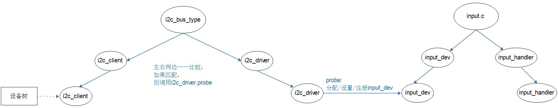
这种框架也是类似的,在 i2c driver 中分配设置注册 input_dev, 同样,这样 i2c driver 也是内核中有,或者厂商提供,我们正常只需要配置设备树,然后系统自动转化为 i2c client.
i2c driver 中,除了分配设置注册 input_dev,还要配置中断,然后在中断处理中,使用 i2c_transfer 获取值,然后再上报数值。
设备树
设备树框架
i2c@00000000 {
    /* ... */

    gt928@5d {
        compatible = "goodix,gt928";
        reg = <0x5d>;
        interrupt-parent = <&gpio>;
        interrupts = <0 0>;

        irq-gpios = <&gpio1 0 0>;
        reset-gpios = <&gpio1 1 0>;
    };

    /* ... */
};i2c@00000000指定 i2c 适配器gt928@5di2c client, i2c 地址是 5dcompatible = "goodix,gt928";reg = <0x5d>;用到的 i2c 地址,io 资源- interrupts 相关
实际设备树
&i2c2 {
    gt9xx@5d {
            compatible = "goodix,gt9xx";
            reg = <0x5d>;
            status = "okay";
            interrupt-parent = <&gpio1>;
            interrupts = <5 IRQ_TYPE_EDGE_FALLING>;
            pinctrl-names = "default";
            pinctrl-0 = <&pinctrl_tsc_reset &pinctrl_touchscreen_int>;
            /*pinctrl-1 = <&pinctrl_tsc_irq>;*/
            /*
             pinctrl-names = "default", "int-output-low", "int-output-high", "int-input";
             pinctrl-0 = <&ts_int_default>;
             pinctrl-1 = <&ts_int_output_low>;
             pinctrl-2 = <&ts_int_output_high>;
             pinctrl-3 = <&ts_int_input>;
            */
            reset-gpios = <&gpio5 2 GPIO_ACTIVE_LOW>;
            irq-gpios = <&gpio1 5 IRQ_TYPE_EDGE_FALLING>;
            irq-flags = <2>;                /*1:rising 2: falling*/

            touchscreen-max-id = <5>;
            touchscreen-size-x = <800>;
            touchscreen-size-y = <480>;
            touchscreen-max-w = <1024>;
            touchscreen-max-p = <1024>;
            /*touchscreen-key-map = <172>, <158>;*/ /*KEY_HOMEPAGE, KEY_BACK*/

            goodix,type-a-report = <0>;
            goodix,driver-send-cfg = <0>;
            goodix,create-wr-node = <1>;
            goodix,wakeup-with-reset = <0>;
            goodix,resume-in-workqueue = <0>;
            goodix,int-sync = <0>;
            goodix,swap-x2y = <0>;
            goodix,esd-protect = <0>;
            goodix,pen-suppress-finger = <0>;
            goodix,auto-update = <0>;
            goodix,auto-update-cfg = <0>;
            goodix,power-off-sleep = <0>;
            /* ...... */
    };
};
源码
drivers\input\touchscreen\gt9xx\gt9xx.c
gtp_probe
static int gtp_probe(struct i2c_client *client, const struct i2c_device_id *id)
ret = gtp_request_input_dev(ts);分配设置注册 input_devret = gtp_request_irq(ts);设置中断static int gtp_request_irq(struct goodix_ts_data *ts)ret = request_threaded_irq(ts->client->irq, NULL, gtp_irq_handler, ts->pdata->irq_flags | IRQF_ONESHOT, ts->client->name, ts);注册线程化中断处理函数,中断下半部使用线程来处理。中断上半截是 NULL,中断下半截是 gtp_irq_handler
中断
static irqreturn_t gtp_irq_handler(int irq, void *dev_id)中调用gtp_work_func(ts);static void gtp_work_func(struct goodix_ts_data *ts)中是实际的中断处理point_state = gtp_get_points(ts, points, &key_value);获取 i2c 数据。gtp_get_points -> gtp_i2c_read -> i2c_transfergtp_mt_slot_report(ts, point_state & 0x0f, points);上报触摸数据。input_mt_slot(ts->input_dev, points->id);input_mt_report_slot_state(ts->input_dev, MT_TOOL_PEN, true);input_report_abs(ts->input_dev, ABS_MT_POSITION_X, points->x);
UInput分析
UInput 属于用户可以用一个模拟的输入设备进行输入。
参考资料:
- Linux 5.x内核
- Documentation\input\uinput.rst
- drivers\input\misc\uinput.c
- Linux 4.x内核
- 内核没有对应文档
- drivers\input\misc\uinput.c
框架
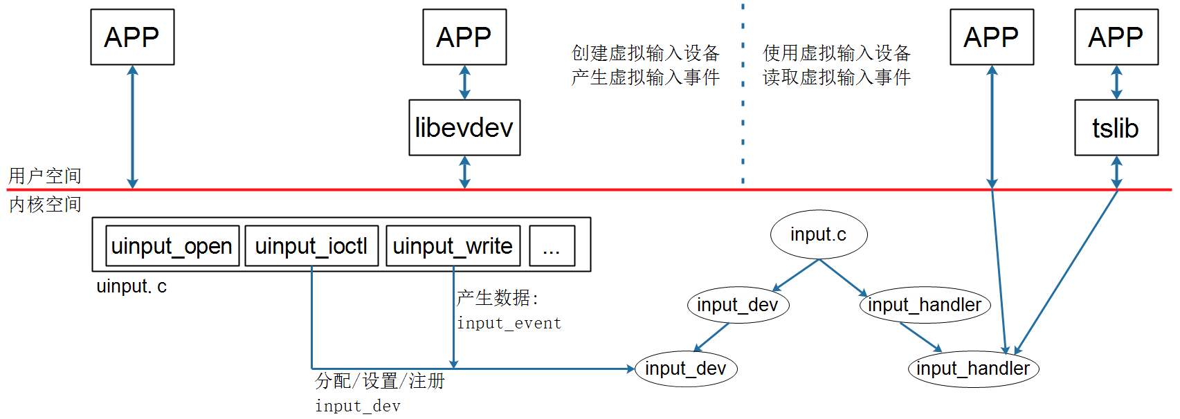
左侧 app 通过 uinput 的驱动程序,open, ioctl 分配设置注册了 input_dev; 通过 write 写入数据,然后驱动程序通过 input_event 上报数据。右侧的 app 就可以直接使用这些按键数据。
源码
drivers\input\misc\uinput.c
uinput_open
static int uinput_open(struct inode *inode, struct file *file)
uinput_ioctl
static long uinput_ioctl(struct file *file, unsigned int cmd, unsigned long arg)->uinput_ioctl_handler(file, cmd, arg, (void __user *)arg);static long uinput_ioctl_handler(struct file *file, unsigned int cmd, unsigned long arg, void __user *p)retval = uinput_allocate_device(udev);其中udev->dev = input_allocate_device();input_set_drvdata(udev->dev, udev);分配 input_dev
switch (cmd)这里面就是根据 cmd 来设置 input 相关位。 app 里面正常可以使用以下这些设置:ioctl(fd, UI_SET_PROPBIT, INPUT_PROP_DIRECT);触摸屏模式ioctl(fd, UI_SET_EVBIT, EV_KEY);ioctl(fd, UI_SET_KEYBIT, BTN_TOUCH);使能按键ioctl(fd, UI_SET_EVBIT, EV_ABS);ioctl(fd, UI_SET_ABSBIT, ABS_X);ioctl(fd, UI_SET_ABSBIT, ABS_Y);使能触摸。ioctl(fd, UI_DEV_SETUP, &usetup);ioctl(fd, UI_DEV_CREATE);设置并创建 uinput.
- app 中的
UI_DEV_CREATE对应的是uinput_create_device(udev);,static int uinput_create_device(struct uinput_device *udev)error = input_register_device(udev->dev);注册 input_dev
- app 中的
ioctl(fd, UI_DEV_DESTROY);对应的是uinput_destroy_device(udev); - app 中的
close(fd);对应的是uinput_release函数,其中也调用了uinput_destroy_device(udev);
uinput_write
static ssize_t uinput_write(struct file *file, const char __user *buffer, size_t count, loff_t *ppos)
uinput_inject_events(udev, buffer, count)input_event_from_user(buffer + bytes, &ev)获取数据input_event(udev->dev, ev.type, ev.code, ev.value);上报数据。
调试
- 别忘了内核要开
Device Drivers -> Input device support -> Generic input layer -> Miscellaneous devices -> <M> User level driver support - 如果设备上已经有了一个真实的触摸屏,那么在开启 uinput 之后,需要通过
export TSLIB_TSDEVICE=/dev/input/event3来手动指定用哪个触摸屏用于 app 测试。
100ASK_IMX6ULL板子上支持其他型号的屏幕
lcd
- 找到 imx 厂家对应 lcd 尺寸的 dts
- 移植 lcd 节点相关内容到板子对应的 dts
- 如果有需要,可以按照 lcd 和 芯片规格书,调整 lcd 时序等参数。
调试
如果想要调试复位引脚:
# GPIO3_IO04在GPIO子系统中编号为:(3-1)*32+4=68,它是第68号GPIO。
$ fb-test                                          // LCD上应该显示红绿蓝色块
$ echo  68 > /sys/class/gpio/export                  // 导出68号GPIO
$ echo out > /sys/class/gpio/gpio68/direction          // 设置为输出引脚
$ echo 0 > /sys/class/gpio/gpio68/value              // 让它输出0
$ echo 1 > /sys/class/gpio/gpio68/value              // 让它输出1
$ echo  68 > /sys/class/gpio/unexport               // unexport
如果手动调试复位引脚,能够改善屏幕,那就需要在 dts 中,增加复位引脚。
dts
reset-gpios = <&gpio3 4 GPIO_ACTIVE_LOW>; /* 100ask */源码
       /* 100ask */
        printk("100ask, %s %s %d\n", __FILE__, __FUNCTION__, __LINE__);
        rst_gpio = of_get_named_gpio(pdev->dev.of_node, "reset-gpios", 0);
        if (gpio_is_valid(rst_gpio)) {
                ret = gpio_request(rst_gpio, "lcdif_rst");
                if (ret < 0) {
                        dev_err(&pdev->dev,
                                "Failed to request GPIO:%d, ERRNO:%d\n",
                                (s32)rst_gpio, ret);
                } else {
                        gpio_direction_output(rst_gpio, 0);
                        msleep(2);
                        gpio_direction_output(rst_gpio, 1);
                        dev_info(&pdev->dev,  "Success seset LCDIF\n");
                }
        }
触摸屏
有厂商信号
直接按照厂商规格书来。
无厂商信号
i2cdetect -y 1查看 i2c 总线上面的设备,通过插拔触摸屏,确定 i2c 地址arch/arm/boot/dts/下面, grep 一下, i2c 地址。可以参考这个芯片对应的 dts 节点。
i2c 控制器
- 先找找 soc 厂商的 dts 中有没有这个 i2c 地址相关的节点,有的话,就复制过来,然后按照现有触摸屏节点,或者 pcba 去修改相关的引脚。
源码
- 根据 dts 中,哪个 i2c 的 compatible 去
drivers/input/touchscreen/中搜索有没有匹配的驱动源码。 - 找到源码之后,去内核中,开启这个驱动选项
tslib 调试
- 先关闭现有的屏幕程序
mv /etc/init.d/S07hmi /root/, 然后 reboot - 执行
ts_test_mt, 简单看下触摸情况export TSLIB_TSDEVICE=/dev/input/event1 export TSLIB_CONFFILE=/etc/ts.conf export TSLIB_CALIBFILE=/etc/pointercal export TSLIB_PLUGINDIR=/usr/lib/ts ts_test_mt ts_print_raw有更加详细的触摸数据打印。
xy 对调
配置文件
/etc/ts.conf 中新增 module linear xyswap
设备树
dts 中,新增 touchscreen-swapped-x-y=<1>;
xy 反向
配置文件
/etc/ts.conf 中新增 module invert x0=1024 y0=600, x 0和1024对调,y 0和600对调
设备树
可以参考 Documentation/devicetree/bindings/input/touchscreen
dts 中,新增
touchscreen-inverted-x = <1>;
touchscreen-inverted-y = <1>;
固件更新
如果要禁止驱动去修改配置信息: goodix,driver-send-cfg = <0>;
总结
正常情况下,input 只需要修改 dts。 特殊情况下,需要新增一个驱动,在驱动中,读取 dts,然后分配设置注册 input_dev,中断里面上报数据即可。
如果是 i2c 的,那么用 i2c_client 那一套;如果是 gpio 那一套,那就走 platform_bus 那一套。
